GICAM sells various types of signal converter. We have signal converters that transmit serial protocols by radio frequencies, very simple to program and control. Our converters are suitable for use in industry. We offer signal converters that transform analog input signals into standardized analog signals, and signal converters that can be connected to devices that have RS-485 or RS-422 protocols.
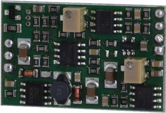
4 – 20 mA CONVERTER
![]() Click to enlarge image
Click to enlarge image

| Board power supply | 12-30 V dc | |
| Cell power supply | 4 V dc per cell (1 cell of 350 Ω or 700 Ω) protected against short circuit | |
| Power assumption | 0.6W with 350 Ohm cell | |
| Output | 4 mA ÷ 20 mA (load <=250W) | |
| Input sensitivity | 1 – 2 mV / V depending on resistance R3 (15 ppm): 1mV/V with R3 = 200 Ω, 2 mV / V without R3 | |
| Dimensions | 35 x 22 x 8 mm | |
| Connections | Wires to be welded | |
| Cell connection | With 4 wires | |
| Storage temperature | - 10 °C / + 50 °C (14 °F / 122 °F) | |
| Operating temperature | - 20 °C / + 60 °C (- 4 °F / 140 °F) | |
| Linearity | 0.02% | |
| Thermal stability | 30 ppm/°C | |
| Zero adjustment | ± 10% full scale through multi-turn trimmer | |
| Gain adjustment | ±10% of full scale using multi-turn trimmer | |
| Analog Filter | 50 Hz | |
| Protection from incorrect connections | Reverse polarity protection of the power supply, short-circuit protection on the mA signal | |
| Type | SG02 Connection |
| Length | ND |
| 1 | + Exc. Load cell |
| 2 | + Signal load cell |
| 3 | - Signal load cell |
| 4 | - Exc. Load cell |
| 5 | + Power Supply 12 - 30 Vcc |
| 6 | - Power Supply |
| 7 | Output 4 - 20 mA (the output GND is power pin 6) |
General precautions to be followed in the installation and assembly of load cells: