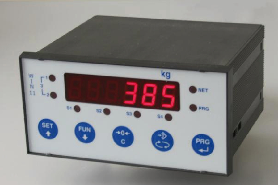
Gicam weight indicators are weight indicator devices connected to load cells. We have multifunction displayers for weighing and dosing, for bridge weighing, with load limiter. Portable displayers are available in comfortable briefcases. We have panel mounting, portable, DIN and OMEGA bar mounts, analog indicators and touch screens indicators. IP65 products are available with dust protection. Gicam indicators support industrial communication protocols like PROFIBUS, PROFINET, MODBUS and more.
Indicator
Download installation and usage manual ![]()
![]() Click to enlarge image
Click to enlarge image

| Power supply | 230 / 115 V ac, 50 / 60 Hz – option 24 V dc | |
| Max power consumption | 7 W | |
| Isolation | Class II | |
| Installation Category | Category II | |
| Operating temperature | -10 / +40°C (14 °F / 104°F) Humidity maximum 85% non-condensing | |
| Storage temperature | -20 / +50°C (-4 / +122°F) | |
| Display | Numeric 6-digit, 7-segment LED (h 14 mm) | |
| Led | 8 5 mm indicator LEDs | |
| Keyboard | 5 mechanical keys | |
| Drilling template | 139 mm X 67 mm (5.47 x 2.64 in) | |
| Built-in depth | 5.31 in (including terminal blocks) | |
| Overall dimensions | 144 x 72 x 120 mm / 5.67 x 2.83 x 4.72 in (l x h x p) (DIN43700) | |
| Mounting | Panel mount | |
| Case material | Selfextinguish Noryl (UL 94 V1) | |
| Protection level | IP 54 | |
| Connections | Pull-out terminal blocks, pitch 5.08 mm (Power supply pitch 7.5 mm) Serial ports on a 9 pin Sub-D | |
| Power supply load cells | 5 V dc / 120 mA (maximum 8 cells with 350 Ω in parallel) protected against short-circuit | |
| Input sensitivity | ≥ 0,02 μV | |
| Linearity | < 0.01% of full scale | |
| Temperature deviation | <0,0003% of full scale/°C | |
| Internal resolution | 24 bit | |
| Weight resolution | Up to 99.999 divisions | |
| Measuring range | -3.9 mV/V - +3.9 mV/V | |
| Digital filter | 0.2 Hz – 50 Hz, selectable | |
| Output rate | From 5 to 50 Hz | |
| Number of weight decimals | from 0 to 4 decimal digit | |
| Zero / FS Calibration | Automatic (theoretical) or executable through buttons | |
| Analog output in tension | Optional: 0 – 10 V / 0 – 5 V | |
| Resolution | 16 bits | |
| Calibration | Digital through keyboard | |
| Impedance | ≥ 10 kΩ | |
| Linearity | 0.03% full scale | |
| Temperature deviation | 0.001% full scale/°C | |
| Analog output under current | Optional: 0 - 20 mA / 4 - 20 mA | |
| Resolution | 16 bits | |
| Calibration | Digital through keyboard | |
| Impedance | ≤ 300 Ω | |
| Linearity | 0.03% full scale | |
| Temperature deviation | 0.001% full scale / °C | |
| Analog input | Connection to contraves or selector (as an alternative to the third input) | |
| Resolution | 10 bits | |
| Logical output | 4 relays (NO contact) maximum 115 V ac / 30 V dc, 0.5 A each | |
| Logical input | 3 opto-isolated at 12 / 24 V dc PNP | |
| Additional logic outputs | 2 external boards of 8 relays (NO contact) max. 115 V ac / 30 V dc, 0.5 A each. | |
| Serial port | COM1: Rs232c half duplex COM2: Rs422/Rs485 half duplex | |
| Max. cable length | 15m (Rs232c) and 1000m (Rs422 and Rs485) | |
| Serial protocols | ASCII, Printers ,Modbus, aquisition from TRF and WST | |
| Baud rate | 1200, 2400, 4800, 9600, 19200, 38400, 115000 selectable | |
| Program code memory | 60 Kbytes FLASH re-programmable on board via RS232 | |
| Data memory | 4 Kbytes | |
| Conforms to standards | EN61000-6-2, EN61000-6-3, EN61010-1, EN45501 | |
| Type | Terminal block 2P (pitch 7.5) |
| Length | ND |
| 1 | 230V~ Line |
| 2 | 230V~ Neutral |
| Type | Terminal block 17P (pitch 5.08) |
| Length | ND |
| 1 | - Exc. Load cell |
| 2 | + Exc. Load cell |
| 3 | + Load cell Sense |
| 4 | - Load cell Sense |
| 5 | - Signal load cell |
| 6 | + signal load cell |
| 7 | - Analog output |
| 8 | + Analog output |
| 9 | Input 1 |
| 10 | Input 2 |
| 11 | Input 3 (analog input option) |
| 12 | Common input |
| 13 | Output 1 |
| 14 | Output 2 |
| 15 | Output 3 |
| 16 | Output 4 |
| 17 | Common output |
| Type | 9 pin Sub-D |
| Length | ND |
| 1 | NC |
| 2 | RS232 Rx |
| 3 | RS232 Tx |
| 4 | RS422 TX+ |
| 5 | GND |
| 6 | RS422 TX- |
| 7 | RS422 RX- |
| 8 | RS232 CTS |
| 9 | RS422 RX+ |
General precautions to be followed in the installation and assembly of load cells: